Hardware
Deciding on what board to buy
ESP8266 is just the name of the chip, many companies have designed their own boards that use this chip, so there are many different ESP8266 boards on the market. If you don't know the difference between all these different models, you might have a hard time deciding on what board to buy.
The easiest (and fastest) way to get an ESP8266 board is to buy one from a well-known electronics shop like Adafruit or SparkFun, but if you want it cheap, you should check out Ebay or other sites where you can order them directly from China.
Development boards
Some boards have all kinds of features on-board to help developing ESP8266 hardware and software: for example, a USB to Serial converter for programming, a 3.3V regulator for power, on-board LEDs for debugging, a voltage divider to scale the analog input ...
If you're a beginner, I would definitely recommend a development board. It's easier to get started if you don't have to worry about all these things.
Bare-bones AI Thinker boards
If you want to add an ESP8266 to a small project, or if you want a cheaper* board, you might want to buy a board that doesn't have these features. In that case, you can buy one of the many ESP-## modules developed by AI Thinker. They contain just the ESP8266 and the necessary components to run it.
To program the board, you'll need an external USB-to-Serial converter.
With some modules, you get an on-board antenna (PCB or ceramic) and an LED, some boards have just an antenna connector, or no LEDs at all. They also differ in physical size, and flash memory size. An important thing to notice, is that some boards do not break out all GPIO pins. For example, the ESP-01 only has 2 I/O pins available (apart from the TX and RX pins), while other modules like the ESP-07 or ESP-12 break out all available I/O pins.
(*) The board itself is cheaper, but you'll have to spend more on external parts.
Overview
Here's a table with some of the most popular ESP8266 development boards and their features:
| Board | GPIO | 3.3V Vreg | USB-to-Serial | Auto-Reset | Auto-Program | Flash | ADC range | Extra |
|---|---|---|---|---|---|---|---|---|
| SparkFun ESP8266 Thing | 11 | + | - | + | ±* | 512KB (4Mb) | 0-1V | Battery charger, crypto element, temperature sensor, light sensor |
| SparkFun ESP8266 Thing - Dev Board | 11 | + | + | + | + | 512KB (4Mb) | 0-1V | |
| Node MCU | 11 | + | + | + | + | 4MB (32Mb) | 0-3.3V | |
| Adafruit Feather HUZZAH with ESP8266 | 11 | + | + | + | + | 4MB (32Mb) | 0-1V | Battery charger |
| Adafruit HUZZAH ESP8266 Breakout | 11 | + | - | - | - | 4MB (32Mb) | 0-1V | 5V-tolerant RX and Reset pins |
| ESP-## | 4 - 11 | - | - | - | - | 512KB (4Mb) – 4MB (32Mb) | 0-1V | Small and cheap |
You can find the full list of ESP-## modules here.
As you can see, both the Node MCU and the Adafruit Feather HUZZAH are solid choices.
(*) When auto-program on the SparkFun ESP8266 Thing is enabled, you can't use the Serial Monitor.
Getting the hardware ready
There are two main categories of ESP8266 boards: development boards with a USB interface (USB-to-Serial convertor) on-board, and boards without a USB connection.
Development boards with a USB interface
For example: NodeMCU, SparkFun ESP8266 Thing - Dev Board, SparkFun Blynk Board, Adafruit Feather HUZZAH with ESP8266 Wi-Fi ...
These boards will show up in Device manager (Windows) or in lsusb (Linux) as soon as you plug them in.
They have a 3.3V regulator on-board, and can be programmed over USB directly, so you don't need any external components to get it working.
The only thing you may need to do, is solder on some headers.
Bare-bones boards and boards without a USB interface
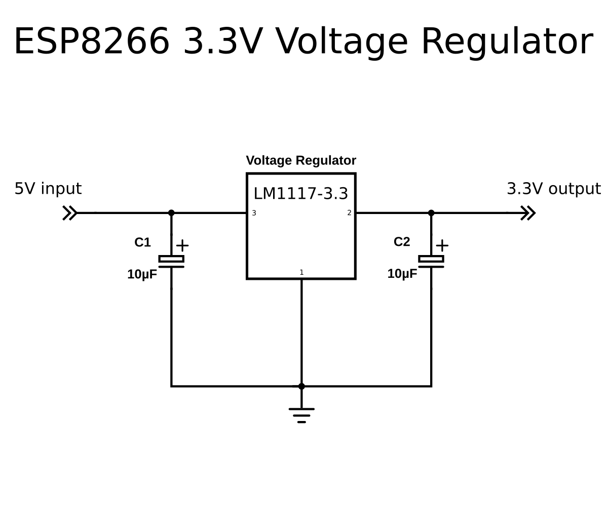
This category has 2 sub-categories: boards with a 3.3V regulator on-board, and boards with just the ESP8266 and a flash memory chip, without 3.3V regulator. If your board doesn't have a 5V to 3.3V regulator, buy one separately. You could use an LM1117-3.3 for example. The on-board 3.3V regulator of most Arduino boards is not powerful enough to power the ESP.
To program the board, you'll need a USB-to-Serial converter. The FTDI FT232RL is quite popular, because it can switch between 5V and 3.3V. It is essential that the USB-to-Serial converter you buy operates at 3.3V. If you buy a 5V model, you will damage the ESP8266.
Connecting the USB-to-Serial converter
- Connect the ground (GND) of the USB-to-Serial converter to the ground of the ESP8266.
- Connect the RX-pin of the USB-to-Serial converter to the TXD pin of the ESP8266. (On some boards, it's labelled TX instead of TXD, but it's the same pin.)
- Connect the TX-pin of the USB-to-Serial converter to the RXD pin of the ESP8266. (On some boards, it's labelled RX instead of RXD, but it's the same pin.)
- If your ESP8266 board has a DTR pin, connect it to the DTR pin of the USB-to-Serial converter. This enables auto-reset when uploading a sketch, more on that later.
Enabling the chip
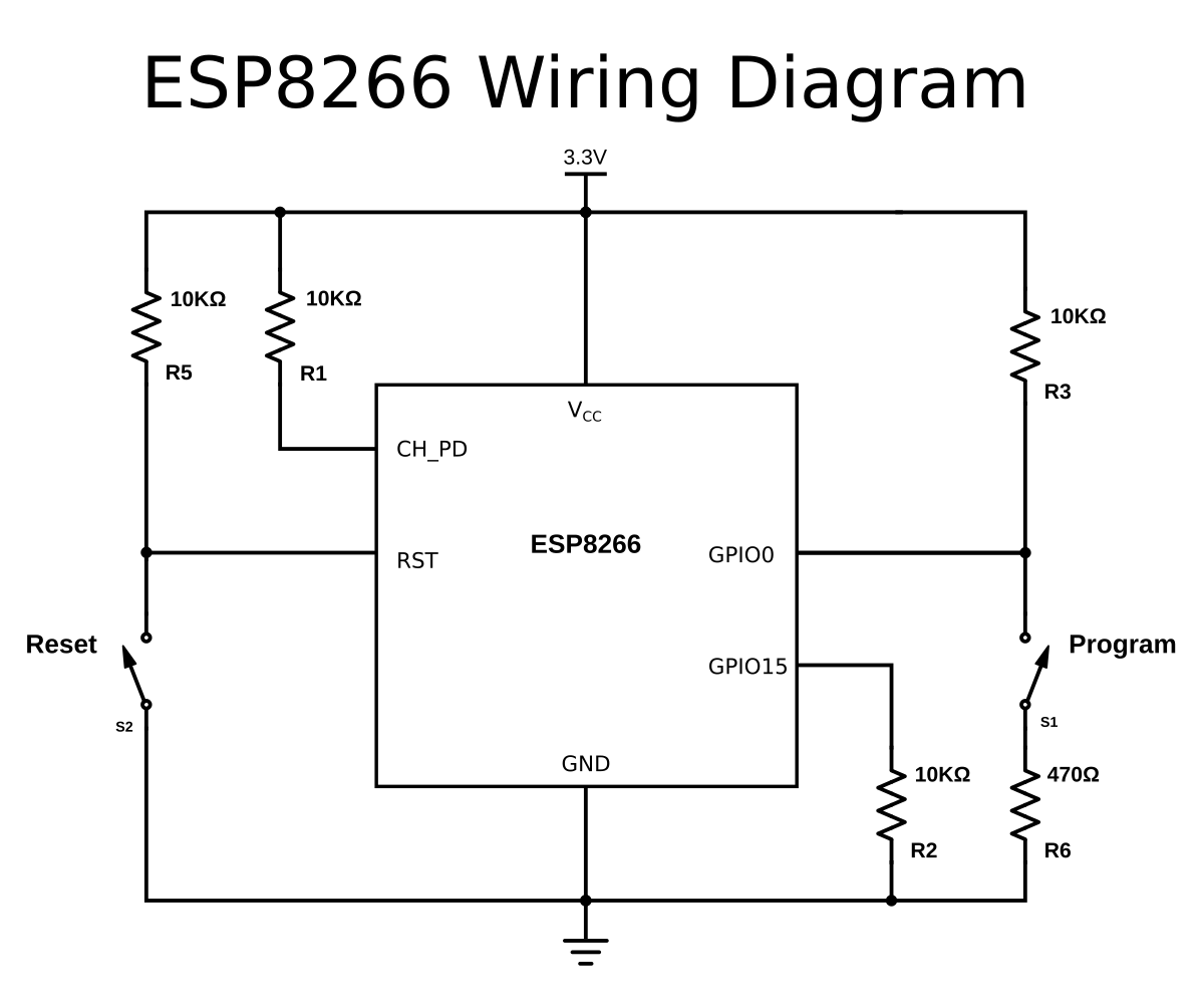
If you're using a bare-bone ESP-## board by AI Thinker, you have to add some resistors to turn on the ESP8266, and to select the right boot mode.
- Enable the chip by connecting the CH_PD (Chip Power Down, sometimes labeled CH_EN or chip enable) pin to VCC through a 10KΩ resistor.
- Disable SD-card boot by connecting GPIO15 to ground through a 10KΩ resistor.
- Select normal boot mode by connecting GPIO0 to VCC through a 10KΩ resistor.
- Prevent random resets by connecting the RST (reset) pin to VCC through a 10KΩ resistor.
- Make sure you don't have anything connected to GPIO2 (more information in the next chapter).
Adding reset and program buttons
If your ESP8266 board doesn't have a reset button, you could add one by connecting a push button to between the RST pin and ground.
To put the chip into programming mode, you have to pull GPIO0 low during startup. That's why we also need a program button. Because it's possible to use GPIO0 as an output, we can't directly short it to ground, that could damage the chip. To prevent this, connect 470Ω resistor in series with the switch. It's important that this resistance is low enough, otherwise, it will be pulled high by the 10KΩ resistor we added in the previous paragraph.
Connecting the power supply
If the ESP8266 module you have doesn't have a 3.3V voltage regulator on board, you have to add one externally. You could use an LM1117-3.3 for example.
- Connect the first pin of the regulator to ground.
- Place a 10µF capacitor between pin 2 (Vout) and ground. Watch the polarity!
- Place a 10µF capacitor between pin 3 (Vin) and ground.
- Connect pin 2 to the 3.3V or VCCof the ESP8266.
- Connect pin 3 to a 5V power source, a USB port, for example.
Before you begin ...
There's a few things you have to look out for when using an ESP8266: The most important thing is that it runs at 3.3V, so if you connect it to a 5V power supply, you'll kill it. Unlike some 3.3V Arduino or Teensy boards, the ESP8266's I/O pins are not 5V tolerant, so if you use a 5V USB-to-Serial converter, or 5V sensors etc. you'll blow it up.
A second thing to keep in mind is that the ESP8266 can only source or sink 12mA per output pin, compared to 20-40mA for most Arduinos.
The ESP8266 has one analog to digital converter, but it has a strange voltage range: 0 - 1V, voltages above 1V might damage the board.
One last thing to keep in mind is that the ESP8266 has to share the system resources and CPU time between your sketch and the Wi-Fi driver. Also, features like PWM, interrupts or I²C are emulated in software, most Arduinos on the other hand, have dedicated hardware parts for these tasks.
For most applications however, this is not too much of an issue.