6. Configuration options and common use cases
Pieter PConfiguration options
The code is very flexible and can be used in many different ways by changing
the configuration options in main.cpp:Config. The settings are
all compile-time constants, resulting in more efficient code and allowing
for useful error messages when some options conflict or are invalid.

// ----------------------------- Configuration ------------------------------ //// Enable MIDI input/output.#define WITH_MIDI 0// Print to the Serial monitor instead of sending actual MIDI messages.#define MIDI_DEBUG 0struct Config {// Print the control loop and interrupt frequencies to Serial at startup:static constexpr bool print_frequencies = true;// Print the setpoint, actual position and control signal to Serial.// Note that this slows down the control loop significantly, it probably// won't work if you are using more than one fader without increasing// `interrupt_divisor`:static constexpr bool print_controller_signals = false;static constexpr uint8_t controller_to_print = 0;// Follow the test reference trajectory (true) or receive the target// position over I²C or Serial (false):static constexpr bool test_reference = false;// Increase this divisor to slow down the test reference:static constexpr uint8_t test_reference_speed_div = 4;// Allow control for tuning and starting experiments over Serial:static constexpr bool serial_control = true;// I²C slave address (zero to disable I²C):static constexpr uint8_t i2c_address = 8;// The baud rate to use for the Serial interface (e.g. for MIDI_DEBUG,// print_controller_signals, serial_control, etc.)static constexpr uint32_t serial_baud_rate = 1000000;// The baud rate to use for MIDI over Serial.// Use 31'250 for MIDI over 5-pin DIN, HIDUINO/USBMidiKliK.// Hairless MIDI uses 115'200 by default.// The included python/SerialMIDI.py script uses 1'000'000.static constexpr uint32_t midi_baud_rate = serial_baud_rate;// Number of faders, must be between 1 and 4:static constexpr size_t num_faders = 1;// Actually drive the motors. If set to false, runs all code as normal, but// doesn't turn on the motors.static constexpr bool enable_controller = true;// Use analog pins (A0, A1, A6, A7) instead of (A0, A1, A2, A3), useful for// saving digital pins on an Arduino Nano:static constexpr bool use_A6_A7 = false;// Use pin A2 instead of D13 as the motor driver pin for the fourth fader.// Allows D13 to be used as overrun indicator, and avoids issues with the// bootloader blinking the LED.// Can only be used if `use_A6_A7` is set to true.static constexpr bool fader_3_A2 = false;// Change the setpoint to the current position when touching the knob.// Useful if your DAW does not send any feedback when manually moving the// fader.static constexpr bool touch_to_current_position = false;// Capacitive touch sensing RC time threshold.// Increase this time constant if the capacitive touch sense is too// sensitive or decrease it if it's not sensitive enough:static constexpr float touch_rc_time_threshold = 150e-6; // seconds// Bit masks of the touch pins (must be on port B):static constexpr uint8_t touch_masks[] = {1 << PB0, 1 << PB1, 1 << PB2,1 << PB4};// Use phase-correct PWM (true) or fast PWM (false), this determines the// timer interrupt frequency, prefer phase-correct PWM with prescaler 1 on// 16 MHz boards, and fast PWM with prescaler 1 on 8 MHz boards, both result// in a PWM and interrupt frequency of 31.250 kHz// (fast PWM is twice as fast):static constexpr bool phase_correct_pwm = true;// The fader position will be sampled once per `interrupt_divisor` timer// interrupts, this determines the sampling frequency of the control loop.// Some examples include 20 → 320 µs, 30 → 480 µs, 60 → 960 µs,// 90 → 1,440 µs, 124 → 2,016 µs, 188 → 3,008 µs, 250 → 4,000 µs.// 60 is the default, because it works with four faders. If you only use// a single fader, you can go as low as 20 because you only need a quarter// of the computations and ADC time:static constexpr uint8_t interrupt_divisor = 60 / (1 + phase_correct_pwm);// The prescaler for the timer, affects PWM and control loop frequencies:static constexpr unsigned prescaler_fac = 1;// The prescaler for the ADC, affects speed of analog readings:static constexpr uint8_t adc_prescaler_fac = 64;// Turn off the motor after this many seconds of inactivity:static constexpr float timeout = 2;// EMA filter factor for fader position filters:static constexpr uint8_t adc_ema_K = 2;// SMA filter length for setpoint filters, improves tracking of ramps if the// setpoint changes in steps (e.g. when the DAW only updates the reference// every 20 ms). Powers of two are significantly faster (e.g. 32 works well):static constexpr uint8_t setpoint_sma_length = 0;// ------------------------ Computed Quantities ------------------------- //// Sampling time of control loop:constexpr static float Ts = 1. * prescaler_fac * interrupt_divisor * 256 *(1 + phase_correct_pwm) / F_CPU;// Frequency at which the interrupt fires:constexpr static float interrupt_freq =1. * F_CPU / prescaler_fac / 256 / (1 + phase_correct_pwm);// Clock speed of the ADC:constexpr static float adc_clock_freq = 1. * F_CPU / adc_prescaler_fac;// Pulse pin D13 if the control loop took too long:constexpr static bool enable_overrun_indicator =num_faders < 4 || fader_3_A2;static_assert(0 < num_faders && num_faders <= 4,"At most four faders supported");static_assert(use_A6_A7 || !fader_3_A2,"Cannot use A2 for motor driver ""and analog input at the same time");static_assert(!WITH_MIDI || !serial_control,"Cannot use MIDI and Serial control at the same time");static_assert(!WITH_MIDI || !print_controller_signals,"Cannot use MIDI while printing controller signals");};
Use cases
Control over I²C
This is the default configuration that is enabled out of the box. It allows
another Arduino to read the position and the touch status of each fader, and
to update the setpoint of each controller. Communication happens over I²C,
and the message format is explained
here.
You can have multiple motor drivers on the same bus by giving them different
addresses, using the i2c_address option.
The included example MIDI-Controller.ino uses this mode, and it can be used as a reference implementation for sending and receiving the right messages.
Control over Serial
The serial_control option is also enabled by default. It allows
you to use the included Python/Tuning.py
script to change the tuning of the controllers on the fly, and to log and
plot their behavior.
See PID Tuning and Architecture: Communication for more details.
Quick test to verify that everything is working
Setting test_reference = true will result in the fader tracking
a test sequence, as shown in the
demo video.
If you also set print_controller_signals = true, you can open
the serial plotter (Ctrl+Shift+L) at the correct baud rate
(serial_baud_rate = 1000000 by default), and view the
reference position, the actual fader position, and the control output, as
shown in the figure below.
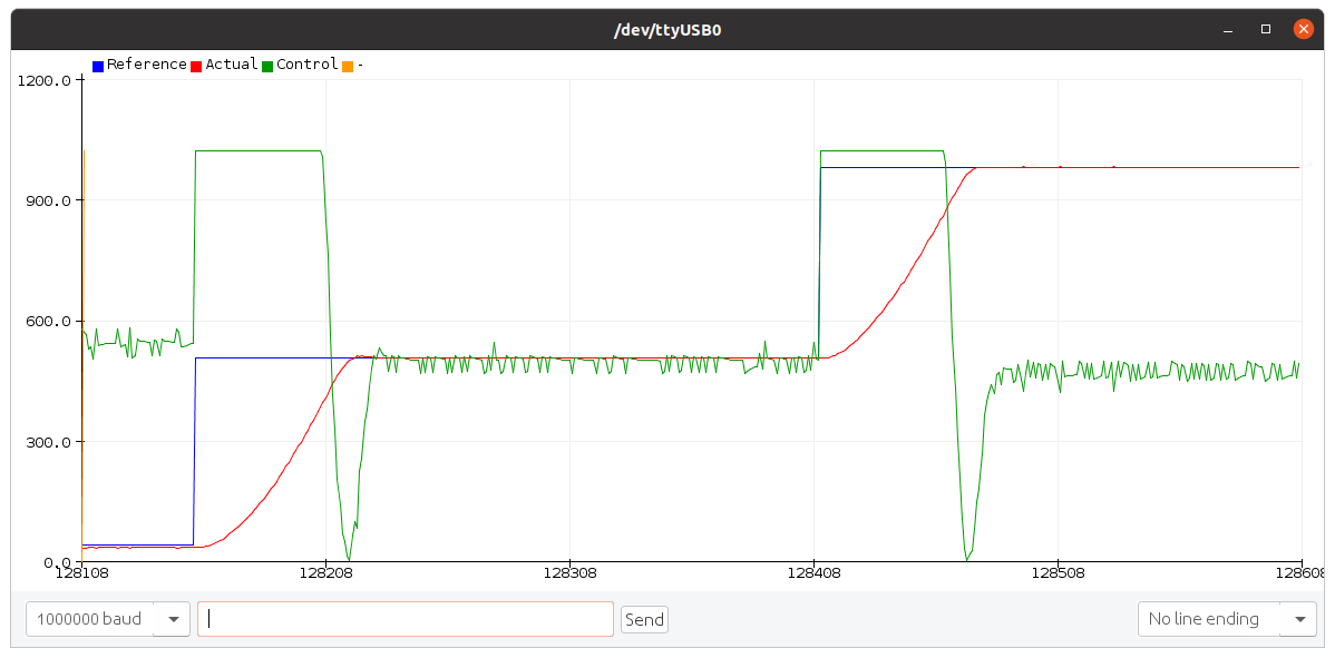
The controller_to_print option specifies the (zero-based) index
of the fader to print/plot the data for.
Direct MIDI control
Although the ATmega328P doesn't have native USB support, it does support
MIDI over Serial. After changing the WITH_MIDI macro to
1 and setting serial_control = false, you can send
MIDI Pitch Bend messages to the serial port of the motor controller to
change the setpoints of the controllers. Fader touch changes are reported
back using MIDI Note On/Off messages, and while touched, the fader positions
are sent as MIDI Pitch Bend messages.
In this mode, you can use the included Python/SerialMIDI.py script to test whether the MIDI communication works correctly. Instructions are at the top of the script (in particular, make sure that the serial port and baud rate are correct).
To use the motor controller directly with 5-pin MIDI or with custom USB MIDI
firmware, you have to select the correct MIDI baud rate: set
midi_baud_rate = 31250.
If you plan to use a software Serial-to-MIDI bridge, you'll have to select
an appropriate baud rate as well. For example, for Hairless MIDI, set
midi_baud_rate = 115200.
Debugging direct MIDI control
The binary MIDI messages can be annoying to debug sometimes, so in addition
to the WITH_MIDI = 1 option described in the previous section,
you can also set MIDI_DEBUG to 1 to make the motor
controller send the MIDI messages as readable text. If you open the serial
monitor at the correct baud rate (serial_baud_rate), you'll
see messages similar to the following when touching and moving the fader:
Note On          Channel: 1	Data 1: 0x68	Data 2: 0x7f
Pitch Bend       Channel: 1	Data 1: 0x30	Data 2: 0x00 (48)
Pitch Bend       Channel: 1	Data 1: 0x40	Data 2: 0x00 (64)
Pitch Bend       Channel: 1	Data 1: 0x50	Data 2: 0x00 (80)
Pitch Bend       Channel: 1	Data 1: 0x60	Data 2: 0x00 (96)
Note Off         Channel: 1	Data 1: 0x68	Data 2: 0x7f
You can also change the setpoint of the faders from the serial monitor.
The format is Ei ll hh (hexadecimal), where i
is the zero-based index of the fader (0-3), ll are the seven
low bits of the 14-bit setpoint, and hh are the seven high bits
of the setpoint.
For example, typing E0 00 40 into the serial monitor and
pressing enter causes the first fader to move to the middle position. For
subsequent setpoint changes to the same fader, you don't have to repeat the
first byte (Ei), and the spaces between the bytes are optional.
For example, first sending E00040 moves the first fader to the
middle position, and then sending 7F7F moves the same fader to
the highest position.
Improved pin assignments for Arduino Nano
The Arduino Nano has additional analog inputs A6 and A7. You can use these
instead of A2 and A3 to make room for two more digital pins. To do so,
set use_A6_A7 = true. You can then use pin A2 for driving the
fourth fader by setting fader_3_A2 = true, thereby freeing up
pin D13 and the built-in LED. See also
Hardware: Connections.