Flashing the ESP8266 with an Arduino UNO
Pieter P
The best way to flash an ESP8266 is by using an ESP8266 development board (e.g. Wemos D1 mini or NodeMCU).
Alternatively, you could use a bare-bones AI-Thinker module, and program it using a USB-to-Serial converter.
If you don't have such a converter, it is possible to use the internal USB-to-Serial converter of an Arduino to flash
the ESP8266. That's what this guide will teach you.
Preparing the Arduino
To flash the ESP8266, we'll use the USB-to-Serial converter of the Arduino. It cannot be disconnected from the Arduino's main microcontroller, so we'll have to make sure that the Arduino is not using the Serial connection while we're flashing the ESP8266. The easiest way is to just upload an empty sketch to the Arduino beforehand (see File > Examples > 01.Basics > BareMinimum).
void setup() { }void loop() { }
Hardware connections
Enabling the chip
If you're using a bare-bone ESP-## board by AI Thinker, you have to add some resistors to turn on the ESP8266, and to select the right boot mode.
- Enable the chip by connecting the CH_PD (Chip Power Down, sometimes labeled CH_EN or chip enable) pin to VCC through a 10KΩ resistor.
- Disable SD-card boot by connecting GPIO15 to ground through a 10KΩ resistor. If your module doesn't have a GPIO15 (e.g. an ESP-01), it is already connected to ground internally, so you don't have to worry about it.
- Select normal boot mode by connecting GPIO0 to VCC through a 10KΩ resistor.
- Prevent random resets by connecting the RST (reset) pin to VCC through a 10KΩ resistor.
- Make sure you don't have anything connected to GPIO2 (more information in the next chapter).
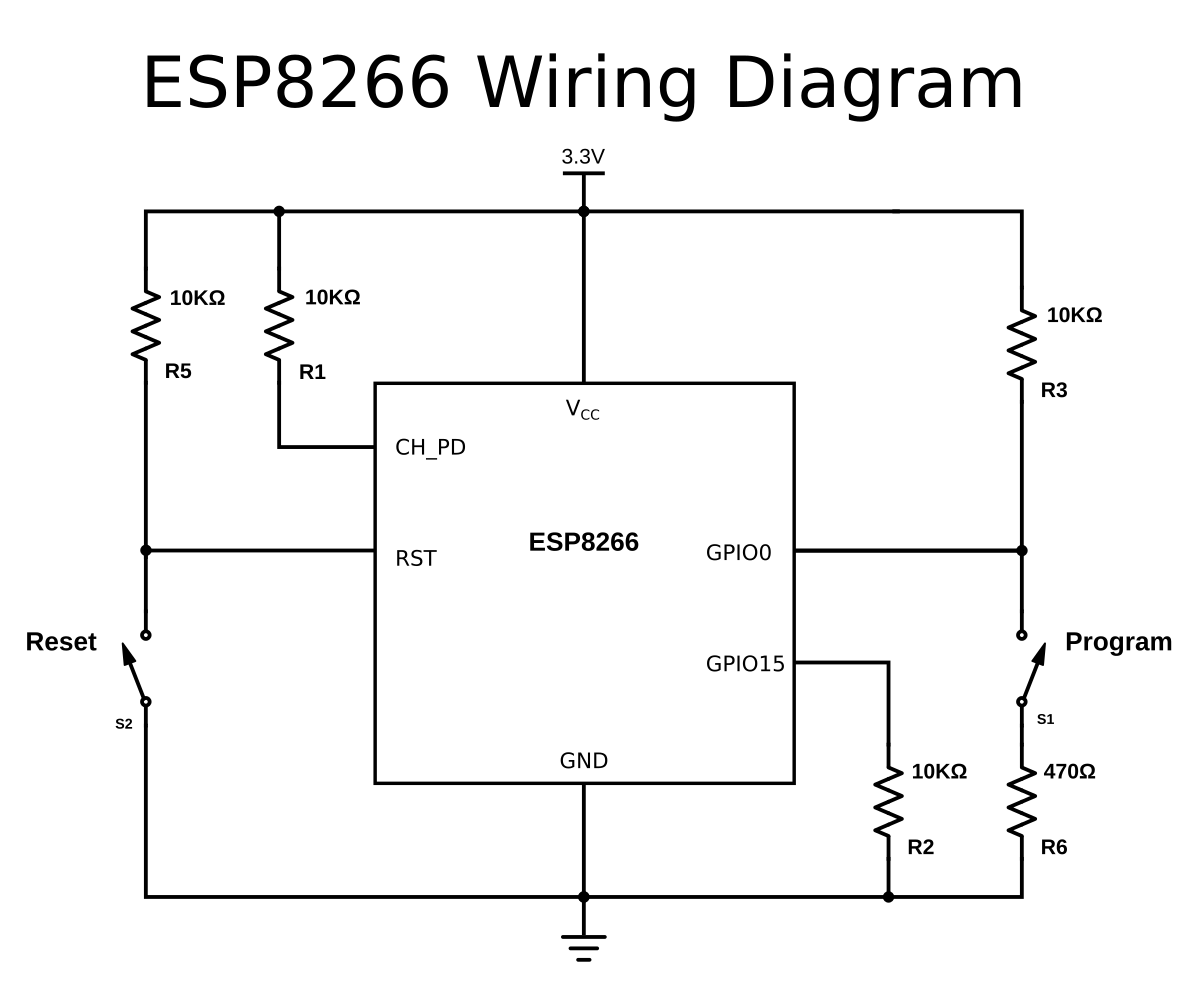
Adding reset and program buttons
If your ESP8266 board doesn't have a reset button, you could add one by connecting a push button to between the RST pin and ground.
To put the chip into programming mode, you have to pull GPIO0 low during startup. That's why we also need a program button. Because it's possible to use GPIO0 as an output, we can't directly short it to ground, as that could damage the chip. To prevent this, connect 470Ω resistor in series with the switch. It's important that this resistance is low enough, otherwise, it will be pulled high by the 10KΩ resistor we added in the previous paragraph.
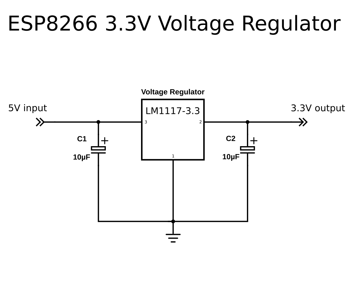
Powering the ESP8266
You need a decent 3.3V power supply, it's not recommended to use the internal 3.3V regulator of the Arduino. You can use
a normal LDO like the LM1117-3.3, for example.
Connecting the serial interface
The next step is to connect the serial interface of the ESP8266 to the USB-to-Serial converter on the Arduino. This is an ATmega16U2, the small square chip next to the USB connector.
Keep in mind that TX and RX lines are swapped in a normal situation. The TX and RX labels on the Arduino board are the TX
and RX pins of the main microcontroller (ATmega328P), and not those of the ATmega16U2.
We need the ATmega16U2, so we'll have to swap RX and TX again when connecting it.
The ESP8266 is a 3.3V device, and the ATmega16U2 on the UNO runs and transmits at 5V. To prevent damage to the ESP8266, we
have to add a level shifter on the transmit pin of the ATmega16U2, to get the voltage level down from 5V to 3.3V. The
easiest way is to connect a 2 kΩ resistor between the Aruino's pin 0 (ATmega16U2 TX) and ground. Together with the on-board
1 kΩ resistors of the Arduino, this will form a voltage divider.
Don't forget to connect the grounds of the ESP8266 and the Arduino together.
Finally, connect pin 0 of the Arduino (ATmega16U2 TX) to the RX or RXD pin of the ESP8266, and pin 1 of the Arduino (ATmega16U2 RX) to the TX or TXD pin of the ESP8266.

Preventing the Arduino from resetting
When opening the USB-to-Serial converter from the computer, the ATmega328P is automatically reset to start the bootloader. We want to prevent this, because we don't want it to interfere with the ESP8266. To disable the automatic reset, it is sufficient to add a 10 µF (or larger) capacitor between the reset pin of the Arduino and ground. If you don't have such a capacitor, you can short the reset pin to ground entirely.
Putting the ESP8266 into programming mode
For the ESP8266 to receive new firmware over the serial port, and for it to program itself, you have to select the correct boot mode. This is done by keeping GPIO0 low during reset.
- Press and hold the reset button
- Press and hold the program button
- Release the reset button, the ESP will boot in program mode
- Release the program button
Uploading the program
Finally, just select the correct board options in the Arduino IDE (select Generic ESP8266 Module as board type, for example), select the Arduino as the serial port to use, and hit upload.
If you get errors like:
warning: espcomm_sync failed
error: espcomm_open failed
error: espcomm_upload_mem failedSporadically, the upload seems to just randomly fail. If that's the case, try a lower baud rate.